
Cantilever Type Steel Structure Welding Robot
| Share | |
|---|---|
| Categories | Steel Structure Welding Robot |
| Brand | YOMI CNC Cutting&Welding Machinery |
| Model | YM-XB-2000-6/9/12X |
| Configuration | Cantilever type (travelling column and boom) welding robot workstation |
| Model | YM-XB-2000-6/9/12X |
| Axes | 6-axis robot plus 1 to 3 travel axes, 6+1 / 6+2 / 6+3 |
| Maximum workpiece size | 13,500 x 3,500 x 2,000 mm (length customisable) |
| Workstation footprint | About 15,000 x 7,000 x 7,000 mm |
| Positioning accuracy | Within 0.2 mm |
| X-axis rail | 15,000 mm, effective about 13,500 mm, up to 0.5 m/s |
| Z-axis payload | Up to 500 kg |
| Welding robot | 6-axis, 6 kg payload, 2,014 mm reach, 0.08 mm repeatability |
| Programming | Teaching-free, driven by STEP/IFC model or laser scan |
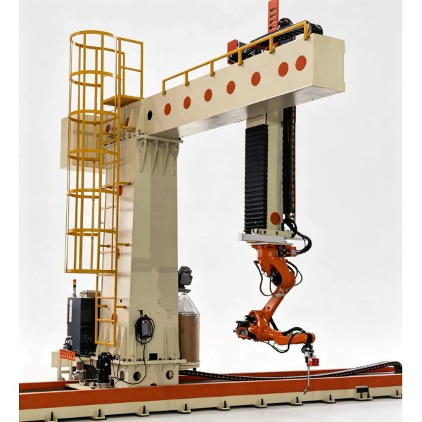
YOMI YM-XB-2000-6/9/12X Cantilever Type Welding Robot
In short: the YOMI YM-XB-2000-6/9/12X is a cantilever type (column-and-boom) intelligent welding robot workstation for steel structures. A 6-axis welding robot is mounted on the end of a powered cantilever boom that runs on a floor rail, giving a 6+1, 6+2 or 6+3 axis machine (7 to 9 axes). It welds either from an imported BIM model (STEP or IFC) or from a laser scan of the real workpiece, so no point-by-point teaching is needed. It reaches workpieces up to 13,500 x 3,500 x 2,000 mm, holds positioning accuracy within 0.2 mm, and can share one rail with a second robot.
What the machine is
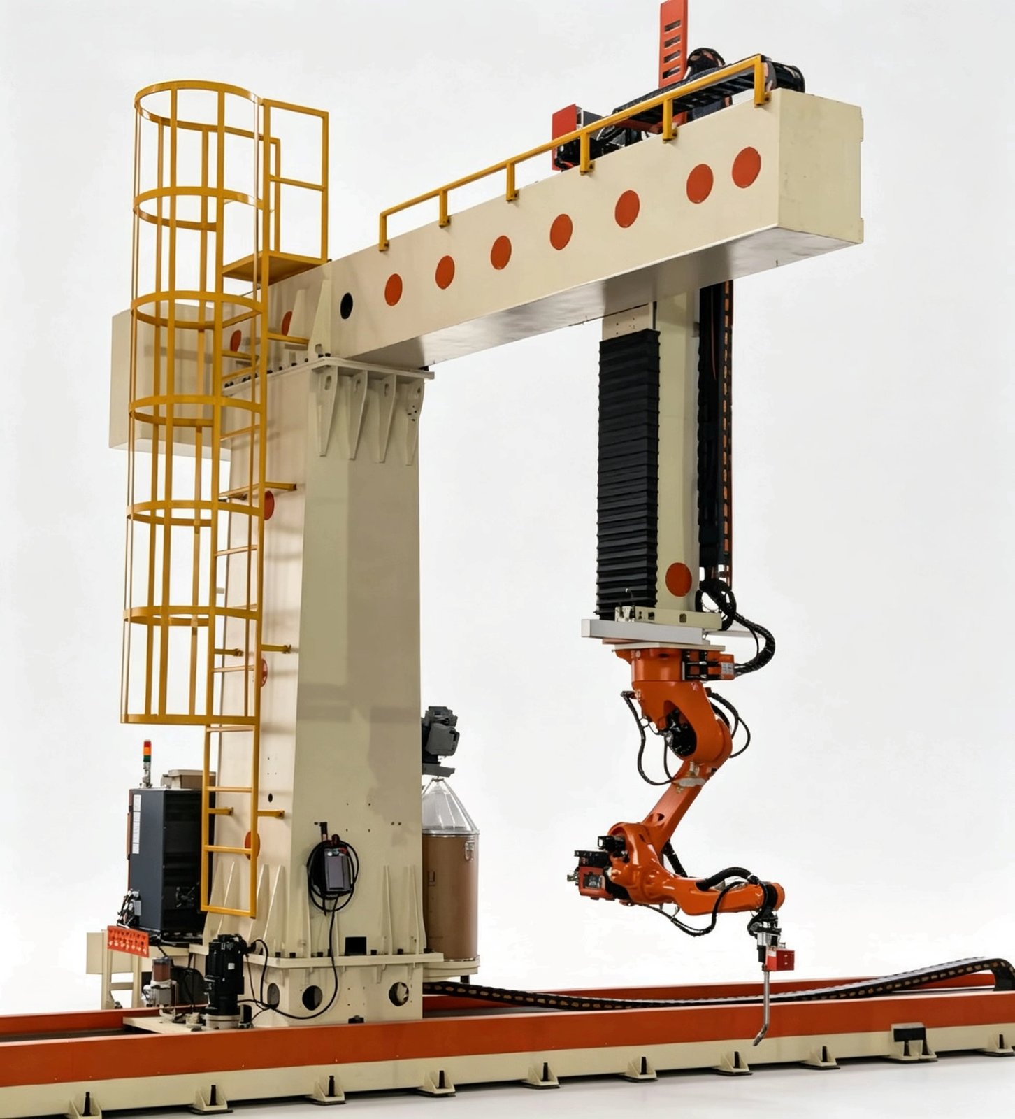
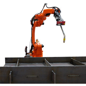
The station is built around a travelling column. The column rides along an X-axis floor rail, the cantilever boom extends in and out on the Y axis, and a vertical Z-axis slide carries the welding robot head. Because the boom reaches out and over the workpiece instead of driving alongside it, the robot can be presented to deep, open steel structures such as H-beam columns, crane beams and transformer tanks.
- Teaching-free welding driven by a 3D model or by in-line laser scanning
- Work envelope up to 13,500 x 3,500 x 2,000 mm on a 15,000 mm rail
- Positioning accuracy within 0.2 mm; Z-axis payload up to 500 kg
- Single-rail dual-machine supported, with built-in anti-collision protection
Key Specifications at a Glance
These are the headline figures for the standard 9-axis cantilever workstation. The same platform is offered in 6, 9 and 12-axis configurations, and the rail length and workpiece envelope can be customised to the workshop layout.
| Model | YM-XB-2000-6/9/12X |
|---|---|
| Type | Cantilever type (travelling column and boom) welding robot workstation |
| Axes | 6-axis robot plus 1 to 3 additional travel axes (6+1 / 6+2 / 6+3) |
| Workstation footprint | About 15,000 x 7,000 x 7,000 mm (L x W x H) |
| Maximum workpiece size | 13,500 x 3,500 x 2,000 mm (L x W x H), length customisable |
| Positioning accuracy | Within 0.2 mm |
| X-axis rail | 15,000 mm long, effective stroke about 13,500 mm, up to 0.5 m/s |
| Y-axis (boom extension) | 2,400 mm effective, up to 0.15 m/s |
| Z-axis (vertical slide) | 1,500 mm effective, up to 0.15 m/s |
| Z-axis payload | Up to 500 kg |
| Station weight | About 8 t including robot, welder and control |
| Welding robot | 6-axis industrial welding robot, 6 kg payload, 2,014 mm reach, within 0.08 mm repeatability |
| Vision system | 3D line-laser camera for seam tracking plus a global line-scan camera for full-workpiece locating |
| Welding equipment | 500 A class power source with water-cooled robot torch and a torch cleaning station |
| Control system | Self-developed welding operating system running on a PC, remote control over TCP/IP |
| Installation environment | 0 to 45 degrees C, 20 to 80 percent RH non-condensing, vibration within 0.05 G |
Two Welding Modes: Model Driven and Reverse Engineering
The workstation supports two ways of generating a welding programme, so it can be used both in digital workshops where a full BIM model exists and in plants where only a physical workpiece and a drawing are available.
Mode A: model driven welding
- The operator imports the 3D model of the workpiece (STEP or IFC); the software parses the geometry and the topological relations.
- A laser line scan performs coarse locating of the real workpiece and confirms how it is actually placed.
- The software extracts the weld seams automatically, matches welding parameters and plans the trajectory.
- Full-path collision detection is run; only after it passes is the programme sent to the robot.
- The robot scans each seam for fine positioning and then welds it.
Mode B: no-model reverse engineering welding
- The operator tack-welds the workpiece at station 1; the robot moves there and the global camera scans the whole part, and can recognise several parts at once.
- The captured point cloud is reverse modelled into a digital twin of the real workpiece.
- The software extracts the weld seams automatically, matches welding parameters and plans the trajectory.
- Full-path collision detection is run; only after it passes is the programme sent to the robot.
- The robot scans each seam for fine positioning and then welds it.
The operating system behind it
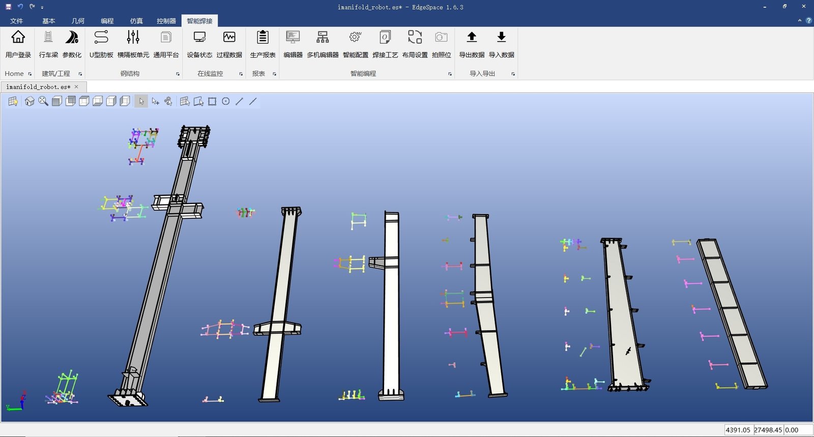
The control software is developed in house around a welding process database. It presents a simulation area, a welding function bar, a manual operation area, a drawing display area and a machine status bar, and it is deployed on a normal PC that can sit anywhere on the network.
- 1:1 simulation environment that pre-calculates cycle time and collisions before the first arc is struck
- Adaptive welding process packs for medium and thick plate, with current tracking, laser tracking, laser seam finding and vision acquisition
- Point-cloud processing for coarse locating, seam identification and reverse modelling
- All based on TCP/IP, so the workstation can be run remotely from an office PC
Core Advantages
Teaching-free programming
Seams are found by scanning and from the model, not by jogging the robot point by point. Programming time drops from hours to minutes, and a new workpiece can be started the same day.
Two modes in one machine
Model-driven welding for digital plants, reverse-engineering welding for sites without a usable 3D model. The same workstation covers both, so it does not depend on data quality.
Full-path collision detection
Every trajectory is checked against the surrounding stiffeners and the fixture before it is sent to the robot, which avoids the expensive crashes that stop production.
Long-reach cantilever
The boom reaches over the workpiece instead of beside it, so 13.5 m long beams, columns, crane beams and tanks can be welded without re-clamping the part.
Stable 0.2 mm accuracy
Ground racks, heavy-duty linear guides and planetary gearboxes on all three travel axes keep positioning accuracy within 0.2 mm along a 15 m rail.
Single-rail dual machine
Two robots can share one rail to raise output, with hardware and software anti-collision protection built in so the two units never interfere.
Wide welding process library
MIG DC and pulse welding, seven weaving patterns, contact wire sensing, laser and arc tracking, multi-layer multi-pass and arc-break restart are all supported.
Manual teaching still available
For narrow spaces or weld joints that a camera cannot reach, the operator can keep using the torch pendant to teach the point, and the robot then applies the matched welding process automatically.
Workstation Configuration
A standard cantilever workstation is delivered as a complete cell, not as a robot on its own, so it can start welding once power, gas and the base plate are ready.
Software system
Intelligent welding operating system, industrial PC and operator console with simulation, seam extraction, collision checking and production reporting.
Vision system
One 3D line-laser camera for seam tracking and one global line-scan camera for full-workpiece locating, both supplied with mounting brackets.
Welding package
500 A class welding power source, water-cooled 500 A robot torch, wire feeder and a torch cleaning station that cleans, cuts the wire and sprays anti-spatter oil.
Travel system
9-axis cantilever travel structure with a 15 m rail, centralised lubrication, fully enclosed bridge-type drag chains, and servo motors of 5.5 kW on X, 2 kW on Y and 3 kW on Z.
Transmission
Hardened module 3 racks and ground pinions, heavy-duty linear guides on all three axes and planetary gearboxes sized per axis for the 500 kg head load.
Safety equipment
Mechanical hard limits plus limit sensors on the travel axes with zero-position marking, so the carriage cannot overrun the rail.
Welding Capability and Application Boundaries
Weld joints it is designed for
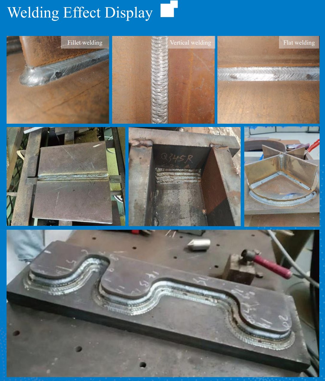
- Flat fillet welds and flat polyline fillet welds
- Vertical fillet welds and corner-wrapping continuous welds
- Lap welds and plane curved welds
- Multi-layer multi-pass welds for medium and thick plate
Practical limits to plan for
- Part-plate intersecting angle should be 70 degrees or more; a sharper angle degrades torch access and weld quality
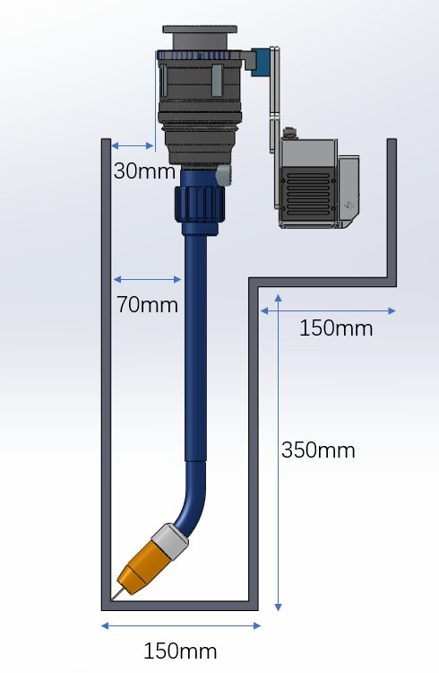
- For flat welding between stiffeners, keep a gap of at least 150 mm
- For vertical welding with the torch held at 0 degrees to the web, keep a gap of at least 450 mm
- Fixture height matters: with the Z-axis at its lowest point the robot base sits 2,400 mm above the floor, so an excessively high fixture reduces the useful Z travel
Seam recognition
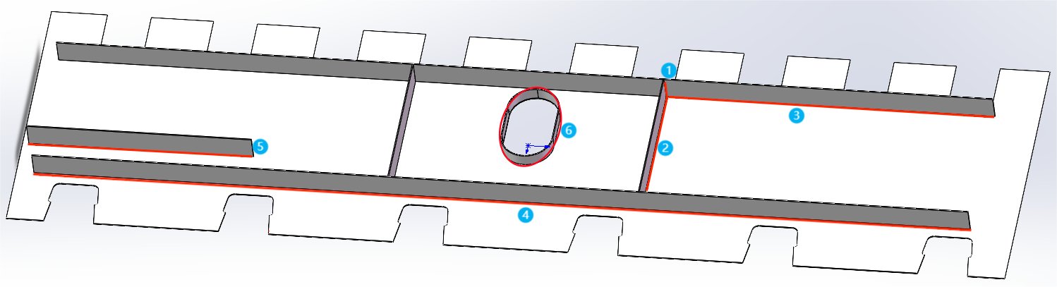
The software identifies fillet, butt and stiffener seams from the model or from the scan, numbers them and plans a welding sequence automatically, so the operator does not key in seam positions.
Weld bead quality
Consistent leg length, smooth ripple and controlled penetration come from parameter matching plus arc tracking, which removes the variation that manual welding introduces between operators.
Machine Structure and Layout
The cantilever layout only needs one side of the workshop free for the rail, which leaves the opposite side clear for handling and storage. The drawings below show the standard 15 m rail configuration.
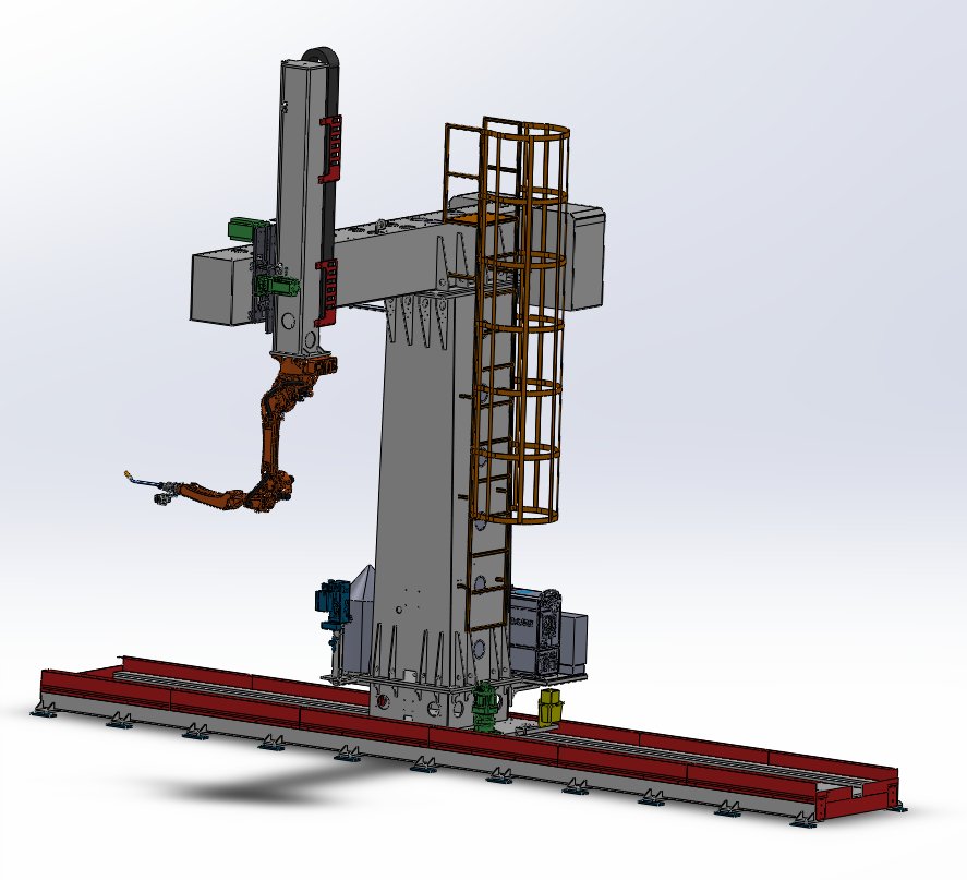
Column and boom assembly
The travelling column carries the boom, the Z-axis slide and the cable management. The robot is mounted at the end of the boom on a rotary mounting plate.
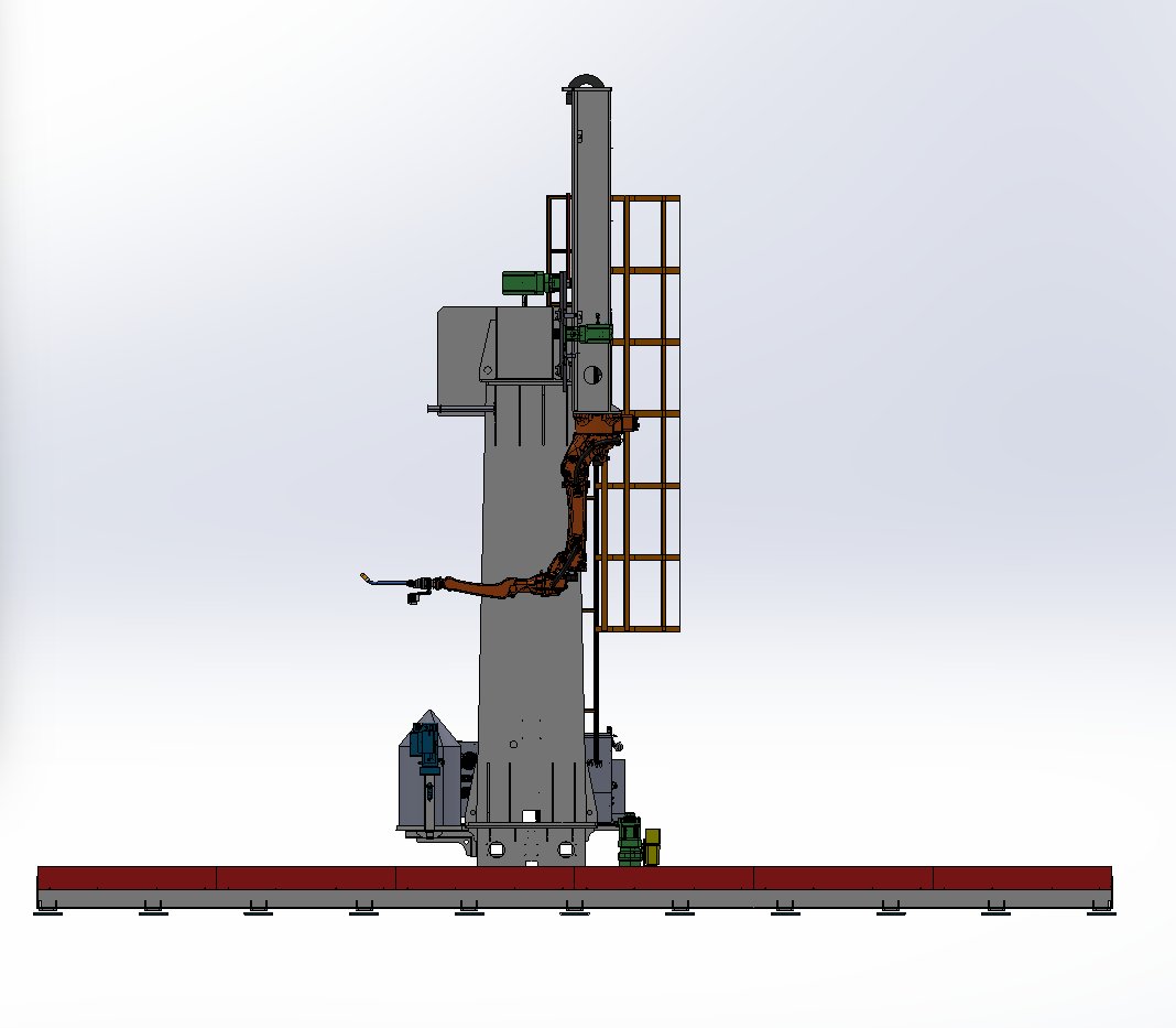
Side elevation
The side view shows the vertical Z-axis stroke and the single floor rail. The boom extends over the workpiece, so the robot can reach the far side of a wide beam.
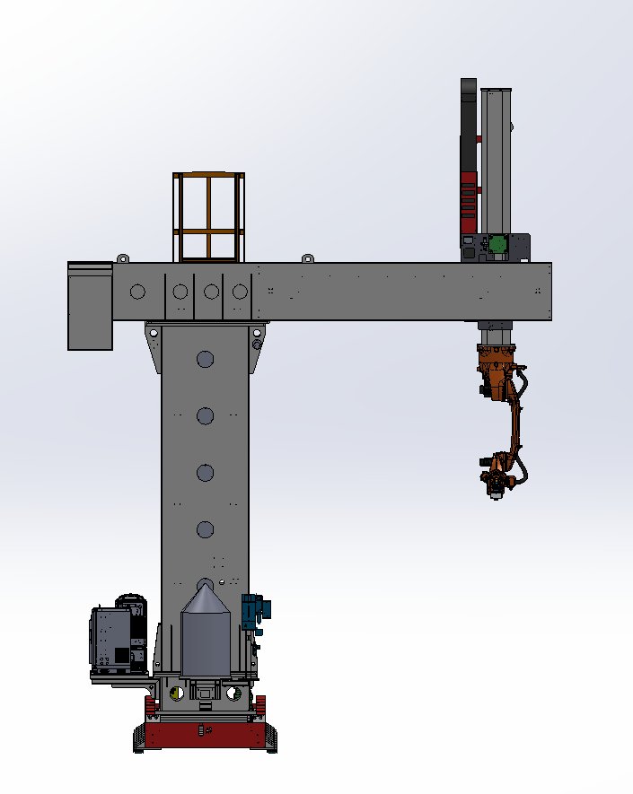
Front elevation
The front view shows the working relationship between the boom, the robot arm and the workpiece, including the headroom needed above the fixture.
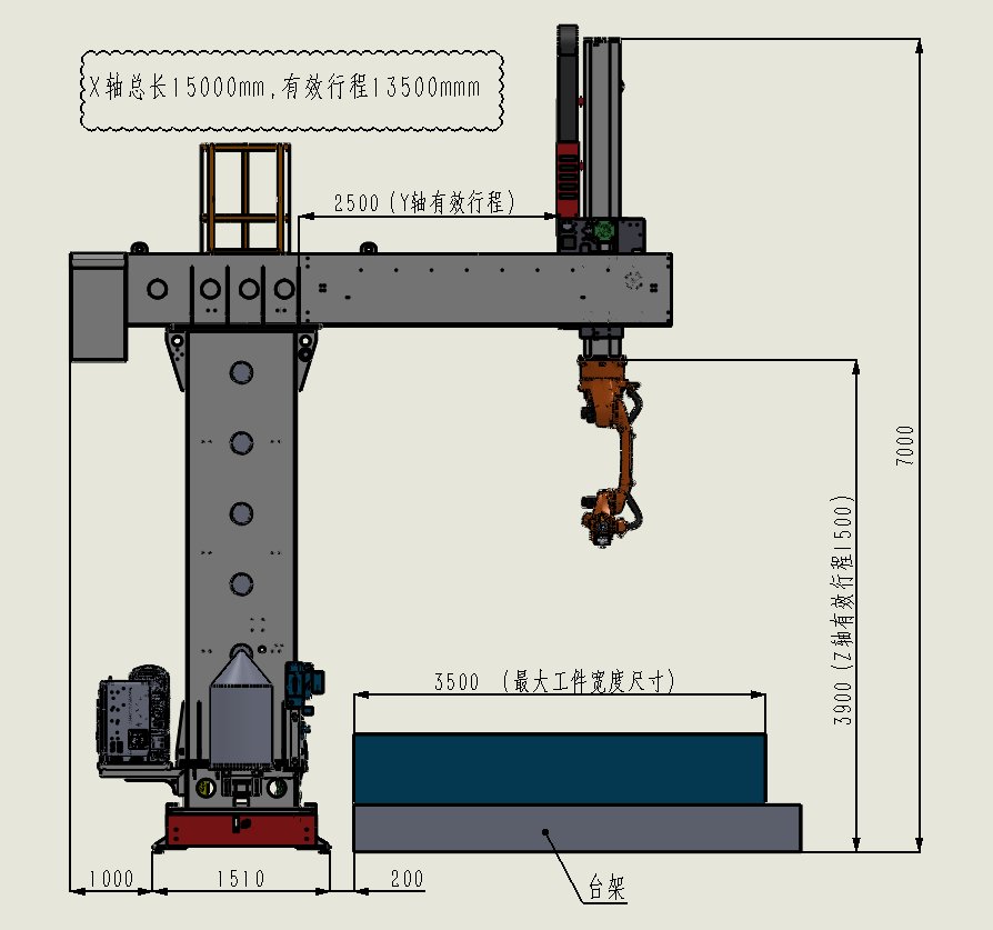
General arrangement
Overall dimensions: 15,000 mm rail with about 13,500 mm effective travel, 2,400 mm boom extension, 1,500 mm Z stroke and roughly 7,000 mm overall height.
Complete Technical Specification
| Structure name | 9-axis cantilever travel system |
|---|---|
| Additional axes | 3 |
| X-axis rail length | 15,000 mm, effective stroke about 13,500 mm |
| X-axis maximum travel speed | 0.5 m/s |
| Y-axis effective length | 2,400 mm |
| Y-axis maximum travel speed | 0.15 m/s |
| Z-axis effective length | 1,500 mm |
| Z-axis maximum travel speed | 0.15 m/s |
| Z-axis payload | Up to 500 kg |
| Positioning accuracy | Within 0.2 mm |
| Servo motors | X axis 5.5 kW, Y axis 2 kW, Z axis 3 kW |
| Rack and pinion | Module 3 rack, precision milled, with ground pinions |
| Gearboxes | Planetary reducers sized per axis, L2 backlash class |
| Linear guides | Heavy duty size 45 on X axis, size 35 on Y and Z axes |
| Lubrication | Centralised lubrication system |
| Cable management | Fully enclosed plus bridge-type drag chain |
| Welding robot | Vertical multi-joint 6-axis, 6 kg payload, 2,014 mm reach, within 0.08 mm repeatability, base weight about 230 kg |
| Robot mounting | Floor and suspended mounting, 3.4 kVA supply |
| Vision camera working distance | 2,000 to 4,000 mm, near field of view 1,750 x 2,800 mm, far field of view 3,000 x 5,000 mm |
| Camera resolution | Z axis within 0.50 mm at 2,000 mm and 2.10 mm at 4,000 mm; up to 6,000 lines per second; anti-glare rated to 180,000 lx |
| Welding torch | 500 A water-cooled robot torch, CO2 100 percent duty cycle at 550 A, wire diameter 0.8 to 1.6 mm |
| Torch cleaning station | Automatic cleaning, wire cutting and anti-spatter spraying, cycle about 4 to 5 seconds |
| Working temperature | 0 to 45 degrees C |
| Working humidity | 20 to 80 percent RH, non-condensing |
| Vibration limit | Within 0.05 G |
| Station weight | About 8 t including robot, welder and control cabinet |
Cantilever, Gantry or Floor Rail: Which Layout Fits
All three layouts use the same teaching-free welding software. The choice is driven by the shape of the workpiece and by how much workshop floor the cell may occupy.
| Consideration | Cantilever type | Gantry type | Floor rail type |
|---|---|---|---|
| How the robot moves | Column travels on one floor rail, boom reaches out over the part | Bridge spans the cell and the robot hangs or rides on it | Robot rides on a low trolley at floor level |
| Work envelope | Very large, up to about 13.5 x 3.5 x 2 m | Very large, and can cover several stations | Long but relatively narrow |
| Floor occupied | One side only, the other side stays clear | Both sides, because of the legs | One side, low profile |
| Best suited to | Long beams, columns, crane beams, tanks and open steel structures | Heavy multi-station lines and box beams | Long H-beams welded in a single line |
| Reaching over the part | Yes, the boom extends across the workpiece | Yes, from above | No, the robot works from one side only |
| Dual machine on one track | Supported, with anti-collision protection | Supported | Supported |
Typical Applications
The cantilever layout was developed for building steel structures, bridges, shipbuilding and energy equipment, where parts are long, open and have many stiffeners.
Building steel structures
H-beam columns, roof beams, crane beams, runway beams, corbels and purlin supports, welded with consistent leg length across the whole run.
Bridges
Bridge diaphragms, stiffeners and girder segments, where the long reach removes the need to reposition the girder during welding.
Shipbuilding
Ship sub-assemblies and block panels, using the reverse-engineering mode where a full 3D model is not available for every block.
Energy and transformer equipment
Transformer oil tanks and similar enclosed frames, where the boom reaches into the open box and welds the internal stiffeners.
Why Buy the Cantilever Welding Robot from YOMI
16 years in steel structure equipment
YOMI has been building cutting, welding, drilling and beveling equipment for steel structure fabrication since 2009, across two factories and nine workshops covering 11,000 square metres.
Exported to over 120 countries
A team of more than 200 people supports installations and after-sales service worldwide, with documented commissioning procedures for each cell.
Certified quality system
ISO 9001 quality management, recognised high-tech enterprise status, more than 100 patents and 6S shop-floor management.
Commissioning and training
The workstation is delivered with process parameter packs for your workpiece families, on-site commissioning and operator training, so the cell reaches production quickly.
Frequently Asked Questions
What is a cantilever type welding robot?
A cantilever welding robot mounts the robot on a boom carried by a travelling column, instead of on a gantry bridge or a low floor trolley. The boom extends out and over the workpiece, so long and open steel structures can be welded from above without moving the part.
Do I have to teach the robot point by point?
No. The workstation is teaching-free in normal production. You either import a STEP or IFC model, or let the global camera scan the real workpiece and reverse model it. The software extracts the seams and plans the path; full-path collision detection is run before the programme reaches the robot. A torch pendant is still provided for unusual joints that need a manually taught point.
What is the largest workpiece it can weld?
The standard cell handles workpieces up to 13,500 x 3,500 x 2,000 mm on a 15,000 mm rail, with a station footprint of about 15,000 x 7,000 x 7,000 mm. Longer workpieces are possible by extending the rail, since the length is customisable.
How accurate is the positioning?
The travel system holds positioning accuracy within 0.2 mm over the rail, and the 6-axis robot itself repeats to within 0.08 mm. Seam-level accuracy is further improved by the 3D laser camera, which scans each seam for fine positioning immediately before welding.
Can it weld without a 3D model or drawings?
Yes. In reverse-engineering mode the operator tack-welds the part at station 1, the robot scans it with the global camera, and the software builds a digital model from the point cloud, including several parts at once. Seams are then extracted from that reconstructed model, so no drawings are needed.
Can two robots share one rail to increase output?
Yes. The system supports single-rail dual-machine operation, and both the hardware and the software include anti-collision protection so the two units cannot interfere with each other.
What are the limits on narrow ribs and deep grooves?
Allow at least 150 mm between stiffeners for flat welding, and at least 450 mm for vertical welding with the torch held at 0 degrees to the web. Part-plate intersecting angles below 70 degrees are not recommended. These are practical values based on the standard water-cooled torch; we will check your actual joint details against them during quotation.
How is the workstation delivered and commissioned?
The cell is shipped as a complete unit: cantilever travel system, robot, vision system, welding package and control cabinet. Installation requires only the base plate, power, shielding gas and compressed air at the site. YOMI provides on-site commissioning and operator training, and the software is configured with welding parameter packs for your workpiece families.
Request a Cantilever Welding Robot Quotation
Send us your typical workpiece drawing, the joint details and the longest part you need to weld. We will confirm the axis configuration, the rail length and the vision and welding package that fit your workshop, and return a quotation with the layout drawing.
- 加载中···
- Name
- Phone
- *Title
- *Content

- Full Name:
- YOMI WhatsAPP
- Tel:
+86 19053498672
- Email:
- sales@yomi-china.com
- WhatsApp:
- 8619053498672
- Address:
- Factory Adress: 9 Changjie Road, Ningjin,Dezhou, P.R.China